Sunday 27 February 2011

FLT page complete

Adding SWITCH/CASE statements to the input handler function of the FLT page finishes off our fully working instrument. At least until testing.

Pressing [SET] toggles the settings mode which replaces some buttons with additional information and adds two arrow keys for adjusting the pitch of the ladder. Pitch can be adjust +-10 degrees. To indicate this 'bias' the waterline takes on a filled "W" appearance and the "-W-" button (when visible) is boxed.

SET sub-mode, adjusting waterline bias
Also a -5 degree bias can be toggled one/off by hitting the "-W-" key.

Some autopilots in Microsoft Flight Simulator allow you to set a HI and LO altitude warning bug. I'm not clear how this is done but for sake of simplicity of control I set the buttons to cycle through some common values that will be prominent in the games mission generator (Cruise height, NOE height etc.).

The "PRES>" button displays current atmospheric pressure at sea level in "inches of mercury". Combat-Helo implements US Standard Atmosphere Model 1976 (wiki) for calculating temperature, pressure and air density for any given altitude.

*edit* Added some slash '/' commands in the in-game chat console to set these bugs. /hibug <feet> and /lobug <feet>


This represents about as much detail as required for this page, completing visual and logical implementation.

-W- waterline bias toggle (on)
Other changes to the logic, calibrated radar altitude to zero when on the ground. Banking no longer results in radar altimeter changes. Bank indicator turns white when helicopter at > 20 degrees of bank.

Bank angle warning > 20 degrees

Here's a video...


*edit* I've since increased the thickness of the pitch ladder to make it much easier to see sitting back.


Post mortem

What seemed like a simple array of standard instruments turned out to be more complex at second glance. Looking at some of the more advanced add-ons for Microsoft Flight Simulator and YouTube videos helped get an idea of how these things should look like in motion.

A week ago we started with a simple screen-shot from a trainer and built a decent replica for our purposes, one component at a time. Much of the logic on the page is in each of these components, very little data exchange is needed. The biggest change I think was adding the atmospheric data to the aircraft Computer class (part of the Avionics sub-class).

Having a small avionics test map allowed for compilation/test/edit in a very small amount of time, typically 10 to 15 seconds build time.

For simply playing the game much of this was not necessary, nor should it be. A player will be able to invest time investigating all these features, or not, their choice.

What comes next?

Well we have some problems with the ENG page since the powerplant simulation evolved into a half-baked set of turbine equations I stole from "Physics for Game Programmers" (published by Apress). Fred might have something better in mind.

The TSD is also a work in progress and important to helicopter operation. Already in game, currently functions as a map but still missing elements. Even worse I don't have a clear specification on what to implement except it can't be too complex. What I DONT want is to have Falcon 4.0 deja-vu, sitting in the cockpit needing a manual just to find where I'm supposed to be going next.

On the subject of the TSD, TSD means Tactical situation Display. you see this in many games, the most conceited one I can think of is the radar in Red Dead Redemption, a top down magic view showing you where to go, where the bad guys are and where points of interest are. It's as simple as that.

My data is scrappy but existing games and simulations do point the way. I have this image from a Discovery Channel video still...


And this from some training software vendor website which is kind of interesting as it's a virtual environment and procedural trainer all in one. Something they didn't often do. I was looking at building such a trainer for crisis training in the Oil and Pipeline industry two years back but I digress.

From some online brochure on training materials.
And it's in GIF format too.

This concludes the FLT page build blog series. Gives you some idea as to the amount of work that goes into making these things from scratch. If I ever have to do it again, I promise I will add more jokes.

Friday 25 February 2011

FLT - flight path indicator and turn co-ordinator

Slip Indicator and rate of turn now implemented. Here's the completed MPD page, when I find my pocket video cam I'll upload a short video of it running.


It needs a wee bit of validation from a pilot who knows how it's supposed to work. Screenshots and theory are one thing. I have to say, I don't really care that much if it's accurate or not. It does the job, if I was being paid to write milspec simulations I'd go the extra nautical but there's a game to finish.

Lets take a closer look at the slip-ball and turn rate elements.

In the "doghouse"
Turn rate and slip-ball 
At no sideways movement or turning the 'ball' should rest between the two vertical lines. It's scaled to show +- 0.5G.

The turn rate indicator is the square sitting in middle of a row of  'doghouses'. It shows the direction of turn and rate. This has a scale of +- 5 degrees per second, when turning left at 5 dps it will hit the left stop. Consequently it often slams against the sides whenever I'm flying.

A couple of hours every night and we have a decent representation of the Apache FLT page. Building it showed some gaps in our simulation variables.


Flight path indicator

I ran over a conversation I had with Fred Naar about the flight-path indicator and adjusting it for different fields of view (PC users tend to have an annoying variety of display sizes, virtualising symbology required melding aircraft velocity with variable fields of view).

The MPD page has a fixed resolution and non-virtual which makes the math is considerably easier (and faster). We can skip a lot of math and resort to velocity divided by the total velocity as a simple offset from the centre.

Vtot is Sqr(Vtot.x * Vtot.x + Vtot.y * Vtot.y + Vtot.z * Vtot.z); // TOTAL VELOCITY


fpx = AirState.Velocity.x / Vtot
fpy = AirState.VelocityGlobal.y / Vtot

This results in an offset we can plot from the centre of the MPD. The only two things we need to consider are total velocities less than 1 (we don't want divide by zeros so we clamp Vtot) and the x/y ratio of the MPD to suit a range pilots will be happy with. I don't have any empirical data on the range of motion consequently it's set it to something I find useful.


To finish off, we'll position the slip and turn co-ordinator.

* edit *

Turn co-ordinator and Slip-Ball math

This is proving to be quite interesting. To calculate the sideways G load for the turn co-ordinator first find the radius of the turn.

   radius = ground_speed ^2 / (9.8 * Tan(bank_angle))

9.8 is a constant (gravity in meters per second)

For a speed of 25 meters per second  and bank angle of 30 degrees that results in a turn radius of 110.46  meters. Double the speed to 50 meters per second and our radius is 441.8 (which is 110.46 * 4). Double the speed the radius is squared. We can verify these results using a handy javascript turn-rate calculator.

To calculate Centripetal force, the sideways force towards the centre of a turn we use:

   centripetal acceleration = velocity ^ 2 / radius

If we use the result of 384 from our above example of 50 meters per second at 30 degrees of bank, we get a force of 5.65 meters per second.

   g force = centripetal acceleration / 9.8

5.65 / 9.8 = 0.58G


At 97 knots, a 30 degree bank creates a 0.58G load.

I need to verify I'm not mixing my units, Fred will have a better idea about the g-force loading so I'll pass that on to him to have a look when he has a free moment.

Wednesday 23 February 2011

FLT - vsi vertical speed indicator

The VSI scale is something of a Swiss-army knife as it conveys multiple amounts of information in a very small space.

Radar altitude is displayed at the mid-point, when below 200 feet a vertical bar moves up and down the scale which represents 200 ft AGL. Additionally a caret (triangle) moves up and down the scale, each small tick marks indicates 100 feet per minute with a maximum climb/descent of 1000 fpm.

Above 1428 AGL the digital display is removed.

Barometric altitude is your altitude above sea level as derived from a reference air-pressure and atmospheric laws. The result is your height above sea level regardless of your height above the ground. This is displayed above the VSI scale. In the example below my test map is at sea level so the baro and radar alt are the same. One of the things we'll do later is add a quick function to change the pressure to adjust this reading.


Another feature is that at some angles of bank, the AGL will vanish when this data is unavailable from the AircraftState (which is what happens when the ground moves out of the line of sight of the the radar altimeter under the aircraft when banking hard).

I'm not too clear what the angle of bank is, but I'm setting it to 30 degrees to match the bank angle indicator.

I noticed an inconsistency between the HMD VSI and the new one. The scale needs some testing with a stopwatch.

*update*

Today seems to have flown by as my laptop fan needed to be put out of my misery. Getting at the fan in a Qosmio X300 seems to require complete disassembly from the top down. In the process I managed to wreck  the surface mount wi-fi connectors, a replacement antenna is on the way. Other than that I managed to get it all back together again with no major difficulty. Except I don't relish doing it all over again next week when the new parts arrive. The fan was truly dying, re-seating with machine oil didn't help.

It's 22:00 in the evening and I'm assessing where I left the FLT page, what's left to do.


  • FPI flight path indicator
  • Virtual waypoint marker
  • Combined Torque
  • Stabiliator gadget
That's more than I thought. Two of those are pretty quick to add. The difficult one, the virtual waypoint marker is a problem, I'm going to leave it out. My reasoning is that I don't have enough data on how it works with and without the video underlay.

The Stabiliator gadget will be handy to see the angle for debug purposes. It's controlled by the model LUA and you send messages to set an angle and it does it's thing. But it can be added later when required.

Lets get to work on the combined torque and FPI.

* edit *

Actually, I don't see an FPI in the source image so I guess I'll leave it out too (even though I just added it, I'll comment out the code).


FLT - pitch ladder

The pitch ladder (sometimes called the artificial horizon) represents the aircraft's angle of bank (left/right) and the angle of pitch (forward/back) relative to the ground.

The finishing touch was to add numerics on the ladder. Now it's looking nearly complete.


And again with the video underlay. I tried it with masked numbers (darkened background) but found that it doesn't look as nice. Digits are aligned correctly with the doglegs on the ladder.


The pop-up repeater is shown bottom right.

Tuesday 22 February 2011

FLT - bank angle

I missed this from the initial spec, the bank angle is above the pitch latter which will be installed next.

The angle of bank indicator is a fixed 60 degree arc. Major ticks every 10 degrees. The aircraft bank is indicated by a small upward arrow under the indicator that points in the direction of the sky. At more than 20 degrees of bank, the scale will turn white.

Bank angle
Drawing such an indicator is trivial: In GLpsuedo code...

   glRotatef(-30,0,0,1);
   { drawTickLine + glRotate(5,0,0,1) } x 13

Airspeed in knots has also been added to act as a reference for the the horizon / waterline.

Moving onto the pitch ladder

The pitch ladder has different properties to the one used in the heads-up display. It's staggered for one, probably uses a circular mask, I might just use a rectangular mask for sake of efficiency, seems a but much to have to add a stencil mask to the buffer just for this. I'm not sure how you do that with a Leadwerks instantiated buffer anyway.

The pitch ladder displays 60 degrees, +-30 degrees in 10 degree increments with small ticks at 5 degrees. In all it consists if four elements

  • There's one horizon line
  • Small ticks (6)
  • 6 Numbered ladder segments
  • Waterline ("It's a big W I tell ya")


The pitch ladder needs an offset applied (bias) set by pressing the "-W-" button. Apparently this is down to pilot preference, some will stick with one method for the duration of their career.

Numbered ladder segments have doglegs pointing to the horizon. Those below the horizon have a dotted or broken appearance.

OK time for tea, we'll get back to this later today and update this entry when we're done.

*update*

Pitch ladder is now in place along with the horizon line and waterline. There's some text to add at the ends of the ladders to indicate degrees. Also I resorted to using a glScissor test to clip the ladder to a rectangular region. I'll replace it with a circular mask if I come up with a fast way of doing it.

Pitch ladder minus text

What's left to do? The VSI vertical scale indicator against the right side. Altitude and combined torque. Then we can go about adding some page logic to add functions to the non-default buttons. We'll finish this off tomorrow.

FLT page - heading tape

Now we're going through our specification, adding elements as we go. I want to talk a little about how I build each element alas time is short today.

The heading tape has been written for the MPD class tonight. And I also added the rest of the button labels which doesn't take long at all. The "A/C" (aircraft) button wasn't in the cockpit database and hence, didn't work at all. This has now been added to all MPDs, this provides a short-cut to the new flight page (unless you're on the ground 'weight on wheels' where it calls the ENG page).

FLT page in progress
The tricky part of the heading tape is masking the area behind the large heading numbers without using stencils or clipping, did it using a logical alpha blending operation. The other problem was adding the offset to the tick marks (of which there are 21).

Assuming I get some time tomorrow I'll start on the new pitch ladder and watermark. Still looking for studio employment (full time only).

Sunday 20 February 2011

FLT page - a study in design pt1

Updated element list with new info 20,02,2011
With thanks to the accuracy police :)


The good folks of the Leadwerks community are hard at work on their "game in a month" projects, I'm really pleased to see so many nice ideas and follow their progress. In the spirit of describing the workflow or design process (and needing to tie up some loose ends) I am documenting the construction of a single avionics page for Combat-Helo, from start to finish.

To outline, our helicopter has numerous digital displays called MPDs (multi-page displays) these show large quantities of information to the pilots in a concise piloty way (I know it's not a real word but if Tony Blair can make up purile words then so can I). It's a good example of an inherited class, a base class for initialising and drawing. And we have the extended class specific to the Apache. The Apache helicopter has five MPDs, it's no surprise we have five instances of the class.

Each MPD has a page and sub-page mode used to tell it what information to present and process. Just like any game menu, it has a render function that contains a SELECT CASE construct to render any given page. You select which page to display by pressing buttons typically arranged around the edges.

Apologies if this is obvious to you the reader, I had to explain this to someone and realised that not everyone  speaks like a geek.

We already have a lot of basic functions in our MPD class for drawing commonly used symbols, vector font, buttons, toggles, events. So all we need to do to add a new page is source our content, replicate it in an overloaded ExtendedDraw() function and add some logic behind it in ProcessEvent()

Wha? Lost already? Suffice to say that each instrument has a draw function, and all inputs such as mouse clicks and network messages directed at that instrument go through an overloaded method which calls the appropriate logic for the current page. For now, lets get down to the content, we're going to build the FLT or Flight page from scratch starting tonight.

FLT - Flight Page

So what does one look like? You can scour Google Images for Apache cockpit (curiously you see a lot of combat-helo images cropping up which doesn't help me at all). Or Aircraft MFDs. Boeing were gracious to send me many years ago a large wall-sized poster of a cockpit but it's a little out of date now. And mono.

From several photos (there's actually some nice YouTube clips too) I will use this one as source for this article, it's from a desktop simulator used for procedural training. As such it's possibly not 100% accurate but we'll run with it.

Picture please....

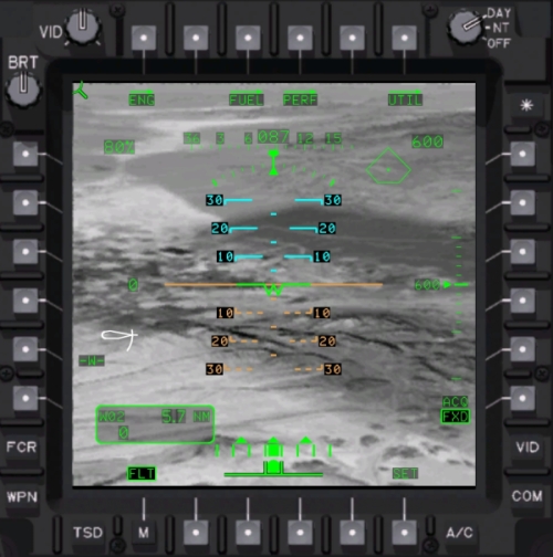
Here's one someone else made earlier
It's quite nice. Shows some colour and importantly (which is why I chose it) a video underlay so you can see what elements of the symbology are masked. The black areas make important data stand out from any video image.

Another thing that stands out is half-intensity masking. I don't have this facility in Combat-Helo since I wasn't aware of it. We'll leave it as something you can adjust with the brightness knob on the display bezel, this is how all pages work by default, the knob controls the alpha of the symbology. Masking is done at the shader level where the video underlay is mixed.

Examining this image we can gather some data. Start by listing what we see.


Elements

1.      Pitch ladder
2.      Heading tape
3.      Radar altimeter
4.      Rate of climb
5.      Altitude digital
6.      Combined Torque %
7.      Slip indicator
8.      Turn rate indicator
9.      Stabilator position
10.  Waypoint Data
11.  Virtual Waypoint and Flight Path Indicator
12.  FLT Page Buttons


Updated

Utility Page Options
·         Switches to same UTIL page used by ENG (engine) mode.

Sub modes
·         SET (settings) adjusts barometric pressure, hi/log bug, G metre.


OK, so far so good. Our images don't tell us about the UTIL page but this swaps to the same UTIL pages as used by the ENG mode. A sub-mode is presented pressing SET (for settings), the same page logic will be used so no special code is required beyond some conditional code that adds the buttons around the page.

Next we go through each element we listed and describe it's behaviour for this page.

Updated


Element Breakdown

1.      Pitch Ladder

Bi-colour, sky is cyan, ground is red/brown.
Provides pitch and roll indication.
Stepped by angle. Digital pitch numerics are masked.
Different from HMD, no head tracking offset.
Waterline “W” provides mid-point reference, can be biased or non-biased.
Biased has it shows a minus 5 degree, on the horizon when on the ground, unbiased will show positive 5 degrees when on the ground. (query: is this bias sent to the HMD system?)
Waterline bias toggled via button #19, SET sub-mode allows manual bias setting.

2.      Heading tape

Same as HMD tape. +- 90 degrees off nose.
3 digit masked heading at centre.

3.      Radar altimeter

As HMD. Tick marks in 10ft increments to 50ft on right, then 50 to 150ft on right.

4.      Rate of climb or VSI

As HMD. Right Triangle indicating climb or descent. Upper scale = 1000  fpm, small tics represent 100 fpm up to 500 fpm.
Digital display of radar altitude. Align right. Blanks at 1428 ft,

5.      Altitude barometric

Barometric altitude readout shown above the VSI scale.

6.      Combined Torque %

Engine 1 and 2 combined torque percentage. Flashes on 12% differential. (ABS(ABS(TQ1)-ABS(TQ2))>12)

7.      Slip indicator

Slip-ball indicator range is +- 0.15G??? Or 0.5G? Need confirmation.

8.      Turn rate indicator

Analogue display of degrees per second of yaw. Scale is +- 5 degrees.

9.      Stabilator position

Indicates literal angle of tail stabilator. I’ve seen this in different colours.
Not displayed when position is automatic.
White, manual control selected.
Yellow, auto mode has failed and must be controlled manually.
Red, airspeed too high for current position.
Question mark indicates unknown angle.

10.  Waypoint Data

As per TSD and MAP page. Same object, selected waypoint, go-to time, distance and ground speed (IGS).

11.  Virtual Waypoint and Flight Path Indicator

This works differently to the HMD implementation. Same object but non-virtual. Positioning the flight path indicator over this symbol will result in the aircraft flying to this point.

Flight Path Indicator, as HMD but non-virtual (use commented out calculation in source).

Elements clipped to main display region (glScissor).

12.  FLT Page Buttons

ENG (engine), FUEL, PERF (performance), UTIL (options), ACQ (acquisition mode) are used elsewhere as direct page callups. M (menu) key is uniform.

Two buttons remain unresolved, “W” (presumably Waterline) and “SET”. W possible toggles an offset to the pitch ladder waterline. I’ve seen this on Boeing simulations but sometimes manufactures of these black boxes do some screwy things just to mess with the pilots heads I'm sure. As in archery, consistency is the aim, and sometimes you shoot yourself in the leg (I won't show that photo).


UTIL sub-mode and SET
            Unknown what sub mode is available in the flight page at this time. I would guess some means to adjust the Waterline offset. Also possible, barometric adjustment and units of measurement.

Since I won’t add these unless we do an advanced pro-simulator I will leave them for now.


That's the end of the first stage. The second stage is usually I get some sleep and remember something I left out, and/or waking up to an emails from angry AH crewmen correcting my wild assumptions, and my editing the blog with thanks to their due diligence in being the accuracy police.


What's next?

On the whole, it shouldn't take too long. Some elements were already constructed and used in the head up display class. The hardest part will be constructing a new pitch ladder and possibly a glyph for the stabiliator (that's the funny white squiggle in the image above, it represents the tail wing position as seen from the side).

Tomorrow I'll review all the elements and make room in the MPD class to take a new page and process its events. Some delay may occur, first it's Sunday and I'm encouraged not to work on Sundays, second my wife has a nasty cold/flu and requires a bit of TLC.

Friday 11 February 2011

Axis Display

As a follow-up to yesterdays blog post just a screen-shot of the axis pop-up I'm using for debugging.

The cross-platform Freejoy library lacks the means to get the OEM string of the device so it required adding a Win32 call to find some registry info or our auto input mapping wouldn't work correctly (since we use this to identify devices).

This should work in most cases however someone may have more than one of the same device. For example a homebrew input device based on a Leo Bodnar USB board. For this there's a port override setting. See I think of everything....almost. I'm sure some of you guys will find a way to break it. *mumble*

As we're not using DirectInput, some axis might be unavailable on some devices. The Windows Multi-Media layer only supports 8 axis and even then the device drivers don't make those available on this layer, the Saitek X65F rotary "F" for example. Nothing I can do about that, it's a matter for the manufacturer and Saitek doesn't answer my emails.


Test Drive Unlimited 2

The new TDU2 from Eden Games published by Atari arrived today. Rather pleased to see they have allowed a bit more freedom to roam around your surroundings on foot. It's quite simple the way it's been done, much simpler than my approach for Combat-Helo, so much so I'm considering dropping such a detailed on foot approach in favour of this. I'm often saying less is more and it would save a chunk of work EXCEPT that I still need the 3rd person animations for AI mobs.

But were a lot a good game ideas in the first TDU, I'm not clear how much Eden Games wanted to exploit them as they seem to have gone in a slightly different direction here. But I've not had much hands on time with the game yet.

Animation

I found my 3D SpaceNavigator mouse and loaded up some assets in MAX only to discover I need to update my exporters. I'm using LE 2.41which changed a little since last time I had to use MAX LE exports. Time to dig out my Blue Book and update the art pipeline notes.

It was funny getting a Twit from 3DConnection (manufacturers of the SpaceNavigator) today. I appreciated that chaps.

 http://www.3dconnexion.co.uk/products/spacenavigator.html

And it does look like it's right out of TRON Legacy. What do you think?


A TRON themed paperweight?
No, a cool 3D mouse.

Thursday 10 February 2011

Joystick inputs and content scripts

Short entry as I'm a bit busy.

Two things planned for this week, character animation export and more campaign coding. Both of which haven't happened at all. Instead I ended up revisiting input functions and audio scripts.

My original script which went through several drafts used a fair amount of UK/NATO vernacular, the opening mission/introduction was turned into a tutorial. New characters were added for mini story arcs and a third pilot character was added for Chinook/AI callouts.

We scripted way more than necessary and even if we can't get all the parts recorded they will as text messages. Working on the details of how elements (or chalks) talk to each other helps crystallize the AI logic. It wasn't until I received  a departure flow-chat that it dawned on me that this might require a bit more work on the event system to deal with all situations. Here's a reduced version you can't read but shows realistic radio traffic is complex. Will be great if we can pull that off, if not for the first release, maybe later.

First draft ATC departure comms protocol (shrunk)
Input functions were re-written at the end of Nov and I found some parts unfinished. It uses a cross platform library but I wanted to be able to plug and unplug joystick hardware and not have any problems. So all attached devices are identified by their OEM strings and assigned a virtual ID. All actions assigned to a particular joystick uses its virtualID and at game launch (or profile load) the actual device ID is allocated if available.

I'd included some fields to shape response curves etc. which I hadn't finished. What I want is a nice 'S' shaped response with a flat middle I can adjust the slope. Just adding that now.

x^2.28

Changing input is easily done if you don't mind editing an XML document. A gui will need to be sorted later for sure. Typical entry might be...

<control name="GAME_SCREENSHOT" type="key" key="CTRL F12" hit="1" />

And it will accept any combination of devices or multiple keys for the same action. And they are also game mode specific. There are separate control schemes for foot, flight, freecam. By organising controls into groups and passing the current game mode to the input functions, the search tree is narrowed down and you have some flexibility.

Also we took some iPhone interface experience and came up with a new way of navigating complex menus using a 360 controller. It's visually engaging and will work for joystick coolie hats too, 100% better than stabbing numbers on a keyboard.

I needed to finish up these new input functions before starting on the character animation. That's your toon walking, running, shooting, sitting, sidestepping. Which is going to be something of an exploration in animation blending with this particular 3D engine. One could try to blend animation with IK (ala Mechwarrior 2) however we're not that heavy a ground combat game. simple artist driven animation will suffice here.

Breaking down what animations are required in Combat-Helo: We're going to restrict ourselves to walking, running, sidestep, death, sitting and shooting. We'll be making use of 3DSMax for exporting individual animations from our US Marine model. Additional skeleton animations can be added later if we keep to using data driven animation for the blending.

Friday 4 February 2011

Russian Helicopters R&D

This week I've had to go back and re-learn some old classes I made and didn't document very well. Specifically a "virtual camera" class which sets up position, rotation, tracking, vibration, TrackIR offsets etc.

A game like ours with multiple view points needs to track where the camera is, the current view might be interior or exterior, might require motion, probably some kind of offset or time based animation. Rather than having multiple cameras and having to do a lot of hiding and showing, parenting and unparenting an abstract camera class was made that took updates, offsets and only applies the end result to the active camera.

I totally forgot about parenting and disobeyed some OO basics (accessing fields outside the class which were supposed to be private). That's now corrected and VirtualCamera properties are updated through the proper member functions. Inline documentation has been added. Slap on the wrist for me. In my defence it's the only class I've done this with and was very much re-written on the fly unlike other elements.

Another thing I did which caused issues was parenting cameras. Parenting objects can cause problems if you have models that use different scales or axis of orientation, or are parented to child objects that have different orientation from it's own parent. It's better I think to set the camera position to the desired object position with and added transform or offset.

Reason for all this camera fiddling was expanding the view system to have a more 'physical' camera that responded to g-forces and clipped against cockpit interiors (rather than passing through geometry). A bit like wearing a helmet.

Research and (some) Development

Going through old papers I found the mass of research (now mostly out of date) for Enemy Engaged Comanche Hokum. In particular the old Ka-52 and Mi-28 helicopters. The Mi-24N and Mi-28N now has glass cockpit features including a modern TADS like system with high-contrast symbology suitable for use with night vision goggles.

Mi-28N 'Havoc' cockpit with, 6x8 function display
If anyone wants to quickly do a translation for me below is a video frame (grabbed from the Wings of Russia series), the Havoc's version of MTADS. The optical tracker is being used to lasing a target, missile is on terminal phase (you can see the dark smoke trail behind the white plume). The target in the dotted 'gate'. I added numbers for reference.

Havoc's night fighting capability, new avionics

The Mi-24 Hind got some love too. I mentioned last year, Farnborough had a Polish Mi-24 on display and it was noted that a more modern cockpit was available (not on that aircraft but in general). Anyway the new glass cockpit looks like it uses the same MFD unit as the Havoc, below is a photo of the Mi-24N layout. Note the all black finish for night operations.

Mi-24N with night capability and new avionics
The panels look quite heavy, 6 buttons left and right with a row of 8 buttons along the bottom. Although I was trying hard to marry up the 8 buttons with the 7 lower fields in the TADS image above. One thing always struck me as odd about the map in the old Mi-24 Hind and the same thing here. In order for the pilot to operate buttons on the right he needs to cross arms or take let go of the cyclic.

None of this means Combat-Helo will have a Russian helicopter anytime soon. It was mostly to see how much of existing avionics code I have can be adapted for helicopters like the Mi-24 (which is a personal favorite).

Things I'm doing this coming week....

It's my birthday on Sunday, I share(d) it with Ronald Regan, perhaps the funniest and best US president I can recall. I'm pushing 42, my youngest daughter keeps saying "You're not getting old, you're turning into an adult." When she first said this I laughed out loud then abruptly stopped as I had to think long and hard about that one.

What is best practice for exporting animated troop models? I've been looking to the Leadwerks community for ideas. The requirement is having a standard set of animations that can be used for all humanoids and documenting the pipeline for an artist. Animating characters in Leadwerks is quite fiddly, it requires authoring a high level function to manage blending different animations for a typical humanoid character. For example, the upper torso might fire a weapon while running, or walking. What I did earlier was create a standard set of strings for animations and have the frame range for a 'walk' defined in the model LUA file. I'll move this out to an XML datafile to facilitate editing. But I want to use the same animations for different models, e.g civilians, pilots, troops.

"Does my bomb look big in this?"
P.S Also continuing with the campaign functions from this last week which are labour intensive.